Friday, April 24, 2015

A Bowden extruder, an E3D clone hotend, and cooling fans

I have been working on the Bowden extruder for the Delta Pi these days. To test the extruder and the hotend before actually installing them in the Delta Pi, I decided to finish assembling my heavily customized Prusa i3 Twelvepro and to design a Prusa i3 X-carriage mount for the Bowden hotend, complete with both an E3D fan duct and a layer fan system. This is the result of my design effort.

The setup as it stood untested, a couple of days ago. The layer fan was not quite reaching the correct position and angle, so I designed some new parts.


You can see the new Z-shaped arm. The fan duct is also new, this is version V3.


Here it is positioned so that the airflow reaches very exactly the extruded material under the tip of the nozzle


Top view of the print head, ready for the first print tests. The left fan is to cool the E3D aluminum body by providing a proper airflow over the fins; it must be connected to the 12V supply and is on whenever the printer is powered. The right fan is the layer fan, controlled by the PWM D9 output on the RAMPS.


And then the long-awaited first print!


This is a calibration object from Thingiverse. As can be observed, retraction was not properly adjusted yet, but apart from that the print came out surprisingly good, all things considered.


These are the parts required for assembling the Bowden extruder (which is a simple remix of Dominik Scholz's design on Thingiverse): basically two relatively small printed parts (the extruder body and the idler), a 608ZZ bearing held in place by a M5 screw and washer, a MK8 gear, a NEMA 17 stepper with good torque (40Ncm), a push-fit Bowden connector, a small spring, and some M3 screws, nut and washers.


Sunday, April 12, 2015

Calibration, sweet calibration

Another video, this one about calibration:


Upgrades!

LED lighting! A new Z-probe! And more!

Saturday, April 11, 2015

A better video

I don't have a Bowden extruder and print head with a hotend to show for yet, but at least I made a better quality video of the Delta Steel plotting/printing the Kossel Mini effector. Here it is:


The noise you can hear (apart from the steppers grinding away) is the pen itself shaking! Printing speed is 60mm/s for perimeters and infills and 100mm/s for travels.

Tuesday, April 7, 2015

First "print"

I have seen this done with a Prusa i3 and I thought I would give it a try with my Delta Steel prototype, until I have my Bowden extruder and hotend ready: use the printer as a plotter by attaching a pen to the carriage/effector. This is quite easy to do with the Kossel Mini effector design that I am using.


The next step was to go through the basic 4-point calibration procedure and adjust the endstop screws on the X, Y and Z carriages, as well as roughly leveling the heatbed. This took a lot longer than I thought it would, I guess because of my inexperience in dealing with linear delta printers. I learned a lot in the process, though, and I'll write about it later in a separate blog post.


After I had reached the point where I could barely insert a small piece of paper under the tip of the pen at the four different points in the calibration procedure, I was ready to test the printer as a plotter, so I sent it the very same Cura-generated and edited G-code that I had used in the previous "in the air" print video. It worked better than I expected:


So this is my first "print" and on the whole, I am quite happy with it!


That, by the way, is the effector that I am using on the Delta Steel itself, as you can see in the first picture above. This is exactly what a RepRap 3D printer should be able to do: print its own parts!

A few details sorted out

I had left a few details to sort out until I got more or less to this point, the purpose of this post is to go over these details, well... in more detail!

Saturday, April 4, 2015

It's alive!


YouTube video coming soon!


In the video the Delta Steel is "printing" the G-code for its own Kossel Mini effector, but to get the Marlin firmware to start printing I had to comment out the temperature setting commands at the top of the G-code file I had generated with Cura. Here is a screenshot of the editor showing my edit:


Note that the printer is printing "in the air", way above the heated bed, because I have not set the correct Z height parameter yet in the Configuration.h file in Marlin. I'll adjust this parameter once I have installed the hotend in the effector.

More vases...

Somehow most developers of (big or small) linear delta printers seem to succumb to the temptation of showing off their design's capabilities by printing vases. Here are some more pictures:

Delta-Pi prototype, 30l print volume, photo by its designer Mike Paauwe

Rostock prototype, 12l print volume, photo by its designer Johann C. Rocholl

Cherry Pi  4XL, 150l print volume, photo by its designer AndyCart


A just-printed vase inside the Raptosaur prototype, 240l print volume, photo by its designer Paul Wanamaker

Friday, April 3, 2015

Wiring the endstops, some soldering required. Also why do I braid wires?

As I mentioned before, the Makerbot-style mechanical endstops I am using come with their cable, but the cable is not long enough, so I had to cut it and add an extra 850mm to each wire (I also braided the endstop cables, see below ). That required some soldering and insulating the solder joints with heat shrink tube.

The endstop cables are routed inside the square stainless steel tubes all the way from the top of the printer down to the RAMPS 1.4 board.


Remember to connect each endstop cable and stepper motor cable to its respective pins on the RAMPS board: Z is the column at the back, X is front left and Y is front right.

Below is the Delta Steel prototype just before I connected the endstops to the RAMPS (obviously I had to lay the printer on its side to do that), with the belts still loose.


Braiding cables

I have this habit of braiding electrical cables

Thursday, April 2, 2015

L-shaped plywood reinforcement

Check the pictures of the Rostock prototype and you'll notice that there is an L-shaped plywood reinforcement at the back of the printer. There is also a similar reinforcement structure used for the Delta-Pi. The Kossel Mini does not need this reinforcement because it is, well... mini, and in fact Johann C. Rocholl hints at this in the RepRap.org wiki page for the Rostock:
A shorter printer may be more rigid / stable and may not need the extra plywood frame on the back and side.
Yesterday I went to buy the wood to reinforce the Delta Steel prototype (which by the way is slightly taller than both the Rostock and the Delta-Pi prototypes), and 15 wood screws later this is what I got:


As can be seen in the picture above, I also got started on one of the belts but didn't tighten it as I was just checking the alignment of the pulleys and through-holes. Everything seems fine at this point so the next step is to route the three belts and tighten them. I am using approximately 195cm of 6mm GT2 belt per column here.

Edit: after tightening the belt and trimming the excess length, I have calculated that I am using approximately 188cm of 6mm GT2 belt per column or 5.64m total.

For the reinforcement structure I am using two wood pieces, the wider one is 16mm MDF like the top and bottom plates, the narrower one is 10mm plywood, as well as 15 x 3x40mm wood screws. The dimensions of the wood pieces are:
  • MDF: 840 x 200 x 16mm.
  • Plywood: 840 x 150 x 10mm.
They are screwed together and to the back right corner of the bottom and top plates to form an L-shaped reinforcement that prevents the printer "tower" from leaning in any direction.


Ugly? Yes indeed. Functional? Absolutely!

Wednesday, April 1, 2015

The humble RepRapDiscount Smart Controller and why I am using it for the Delta Steel

And also a simple stand design for the RepRapDiscount Smart Controller, see below!


In my opinion all 3D printers should be equipped with an LCD controller, for simple practical reasons:
  • An LCD controller gives you immediate visual feedback about the status of your 3D printer.
  • An LCD controller, as its name implies, allows for direct control of the 3D printer, before, during and after the print.
  • An LCD controller which is equipped with an SD card reader allows you to print G-code files from the SD card.
Besides this, it should be noted that LCD controllers are relatively inexpensive components and readily available from a number of suppliers. I have been using "made in China" clones of two different LCD Controller models in my P3Steel's:
  1. The RepRapDiscount Smart Controller which is a 20 characters x 4 lines LCD with a rotary encoder, a buzzer and a stop button.
  2. The RepRapDiscount Full Graphic Smart Controller which is a 128 pixels wide x 64 pixels tall LCD with, again, a rotary encoder, a buzzer and a stop button.
They both work fine with a RAMPS board, displaying as much useful information as one could need or want, both are equipped with an SD card reader and both cost < $15 per unit. For the P3Steel, although I have used both and am equally satisfied with either design, I recommend the RepRapDiscount Full Graphic Smart Controller, simply because it looks slightly better and the price difference is minimal (about $2).

For the Delta Steel I decided to go with the RepRapDiscount Smart Controller. First, it's the same LCD Controller that has been used in the past for many linear delta printer prototypes, including the Delta-Pi prototype itself. And second, there are reports that the Arduino graphics library used to drive the LCD in the RepRapDiscount Full Graphic Smart Controller is CPU intensive and can cause problems when printing at high speeds on a linear delta printer, where the Arduino also has to deal with the Cartesian to delta transformations.

A simple bracket to mount the RepRapDiscount Smart Controller onto any wooden surface

I designed a rather basic bracket to mount the RepRapDiscount Smart Controller onto the MDF base of the Delta Steel prototype, which I have published on Thingiverse.


You'll need to print a mirror pair of these like in the OpenSCAD render above, and they additionally require two M3 10mm screws and nuts and two wood screws.


The main advantage of these brackets versus a complete cover and base is that they use very little material and print very quickly. They are strictly functional though, I didn't attempt to make them aesthetically pleasing in any way.


And did I mention that the knob with the Open Hardware logo is a previous design of mine, published on Thingiverse too?

Tuesday, March 31, 2015

Effector assembly

I printed another, more basic Kossel mini effector of my own design, this is a simple remix of a design by Tobias Kornmayer I found on Thingiverse which thankfully was published with its OpenSCAD source code.


Note that all the various Kossel mini effector designs available on Thingiverse and elsewhere are directly derived from Johann C. Rocholl's original OpenSCAD source released under the GPLV3 (https://github.com/jcrocholl/kossel/blob/master/LICENSE), which requires that any modifications be released with their source code. Unfortunately, many are released just as STL files, hence not complying with the GPLV3 license. When people don't respect and comply with the GPL, we as a community all stand to lose. I intend to write a post regarding these issues later, where I'll explain my point of view in more detail. In the meantime, I have published my effector design remix on Thingiverse with proper attribution, source code and under the GPLV3 license.

Back to the effector itself, it is very thin and lightweight and prints in minutes, not hours:


I then assembled the rods, the effector and the carriages to see how all this fits:


This is starting to look like something!


As far as I can tell, the rods are parallel and 40mm apart, that distance being determined by the Kossel Mini effector, which is what I wanted to achieve when I redesigned the Delta-Pi carriages:


The next step is to install the three GT2 belts and check that they don't rub against any part.

Saturday, March 28, 2015

A jig for the diagonal rods

When calibrating a linear delta 3d Printer it is essential to have all diagonal rods the same length, or at least within close tolerance. The easiest way to achieve this is to assemble the diagonal rods on a jig.


I decided to reuse some of the OpenSCAD code from my earlier Traxxas 5347 ball link assembly tool to design and print the couple of jig posts required for the jig. Then it is just a matter of gluing the posts on a flat surface with one of the rods assembled on it, and then assembling the other five remaining rods on the jig.


By "assembling" I mean just mixing some epoxy glue and gluing the Traxxas connectors and the carbon fiber rods with the printed joiners on the jig, while making sure the Traxxas connectors are on the same plane.

Diagonal rods: done! Their measured length is 372mm.

Friday, March 27, 2015

Assembling the Delta Steel - bottom plate, electronics and steppers. Also some news about the firmware.

Progress on the Delta Steel prototype has been slow but steady these days. I have been working on installing and testing the electronics and the firmware. Here is how the underside of the bottom plate stands now:


The 17HS8401 NEMA 17 steppers come from China, these are 48mm long and are supposed to provide 48 N·cm holding torque at their maximum rated current of 1.8A. I adjusted the DRV8825 drivers for 1.4A peak current per coil or approximately 1A rms for both coils, that should be more than adequate for the Delta Steel. I always recommend the use of a fan blowing some cool air over the electronics, this one is a 12V 80mm LED fan. The three female connectors at the top of the picture correspond to their male counterparts from the ATX power supply.

Regarding the firmware, I have found a patch that allowed me to compile the latest commit from Johann C. Rocholl's GitHub repository. More on that later or check my fork of Johann's Marlin repository.

Wednesday, March 18, 2015

Endstops, Makerbot-style.

The Delta-Pi was designed to use plain mechanical micro switches as endstops, but nowadays a mechanical micro switch costs practically the same as a Makerbot-style mechanical endstop with cable and connectors, which I also use on the P3Steel. The main advantage of the Makerbot-style mechanical endstop is that it includes an LED that lights up when the endstop is triggered. The sole disadvantage I can think of is that it requires three wires (+5V, Ground and Signal), but since they come with a cable, that is a moot issue. Consequently, I re-redesigned the Delta-Pi top clamp:


The assembly requires two M3 10mm screws and two M3 nuts.


When assembled the top clamp looks like this:


The M3 25mm screw on the carriage can be used to provide some fine adjustment to the endstop position.

Sunday, March 15, 2015

The Holy Grail of RepRappers: very large print volume and crazy printing speeds - really?

After reading through many pages in quite a few topics on forums and blogs related to 3D printing, DIY RepRaps and particularly new 3D printer developments, one could conclude that all the exciting new developments as of March 2015 are related to either large print envelope 3D printers or high speed 3D printers, or what would seem to be the Holy Grail of RepRappers: printers that combine both high speed printing and large print envelopes. Hurray, we'll all be printing 50cm tall vases at 500mm/s in the near future!

My quick take on all that: nonsense! In this case, bigger is neither better nor worse, it's just that: bigger. And Fast & Furious won't get you anywhere when applied to 3D printing! Below I explain my point of view on these matters and how they relate to some of the design choices for the Delta Steel.

Very large print envelope 3D printers

First, what on Earth is a "very large" print envelope?

Now that's a large print envelope 3D printer! The Betabram P3, a house printer, image courtesy of 3DPrint.com.
Back to the roots: the Prusa i3 has a theoretical print volume of 200 x 200 x 200mm, quite enough for it to print its own plastic parts, and enough for the vast majority of print jobs that one can reasonably print in less than 24 hours with an average 50mm/s print speed. So let's assume that 8l is a "normal" or "medium size" print envelope.

The P3Steel is a compact Prusa i3 variant with the same theoretical print volume of 200 x 200 x 200mm.
Let's double that (16l) and we have what we could call a "large" print envelope for a desktop 3D printer. The Delta Steel, for example, has a "large" print envelope, since it can print 200 x 200 x 400mm objects - theoretically speaking, of course. That is similar to the print volume of the original Rostock:

The Rostock - image courtesy of the RepRap.org website.
A "very large" print envelope would be something again twice as large i.e. 32l or more. Now, why didn't I aim for a "very large" print envelope for the Delta Steel? All I would need to do would be to use a round heatbed with a 300mm radius, and these are available on AliExpress (hence they don't cost a fortune).

How many vases are you going to print?

The answer is simple: I don't expect to need to print anything larger than what I can already print on my P3Steel, at least in the short term. And I don't think I'll ever use the 400mm maximum print height that I have available on the Delta Steel (actually it's a little bit more than that, but who cares?). Yes, the Rostock, the Kossel, the Delta-Pi and all similar-sized linear delta 3D printers are often pictured printing vases, where the extra height comes in handy:


However, I confess personally I am not so much into printing vases in PLA or ABS - I rather prefer my vases in porcelain or glass and I would rather buy them at the China store than going through the trouble of printing them myself.

Now, apart from vases, surely there must be things that one would like to print that exceed the 8l print envelope of the Prusa i3? Well, you just have to check Thingiverse and look for such objects, from what I have seen there aren't that many (again, apart from tons of different vases...).

The simple truth of the matter is that the Delta Steel inherited its size from the Delta-Pi which in turn inherited its size (roughly speaking) from the Rostock which has a print envelope of 200 x 200 x [200-400]mm (MK2 heatbed area x approximately (column_height - (0.9 x arm length))). And the Rostock inherited the MK2 heatbed from the Prusa i3, of course. So we are back at our starting point.

Scalable 3D printer designs (scaling down is easy, up - not so much)

It used to be that 3d printer developers would come up with a good Open Source design and release it without any grand claims of scalability. Take the Prusa i3 developed by Josef Prusa : the dimensions of the printer are set in OpenSCAD files and they can be changed somewhat from the original values (and you would still end up with a working printer), but Josef Prusa never made any claims that the Prusa i3 design could be scaled up or down, as far as I know. Same goes for Mike Paauwe who designed the Delta-Pi: he does not use the word "scalable" a single time in the documentation for the Delta-Pi.

I went through the Rostock documentation in the RepRap.org wiki and Johann Rocholl did not use the word "scalable" either, although he does mention that the printer can be made taller or shorter:
You can make your Rostock taller or shorter simply by adjusting the length of the smooth rods and timing belts.
That's it. The Kossel, however, was designed as a parametric printer and Johann explicitly mentions the possibility of scaling it down:
Optionally scale down to a Traveling RepRap that fits within IATA hand luggage size limit
So far so good. Now check the following quote from Richard Horne's blog, about the 3DR delta printer based on the Kossel and Tantillus:
"Is 3DR scale-able?" Yes, easy to go taller, just needs some thought about rod length. To go wider you will need to consider rod sizes. I always intended to be able to insert another printed part (spacer) and a new bigger middle triangle to get an overall bigger build area with the same parts. I actually wondered about keeping the size smaller to start with and doing extensions that could be printed out in order for it to be able to self reproduce, but that was getting messy.
And to the person who asked me if it's possible to make a Delta printer 3 Meters tall - YES!, Oh yes!, you can and if you build one (or want me to make you one) - please let me know :)
and in another blog post:
I get asked a lot about building Bigger Delta printers. - Going higher is not a mystery you just extend everything taller. Going wider in X and Y is also quite easy, you just need to also extend the print arms. General relation in size of these arms is the horizontal distance between the vertical posts x 0.8
(emphasis in bold is mine)

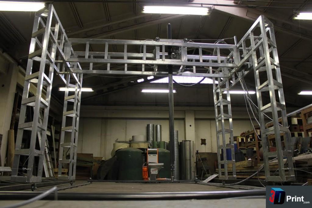
And to prove his point, Richard developed the 3DRmega (seen here not-yet-functioning with an antique mirror in place of a heatbed, as described by the author):


Now, not only the 3DRmega does not look at all like the original 3DR, but its development doesn't seem to have gone quite as Richard expected. This is what he posted in July 2014:
And guess what? When I posted about 3DRmega in February, I had a flood of requests for design files (I posted way too early, sorry) and also hundreds of people saying I should put it up on Kickstarter...
That's enough of the mega for now, I'll post more and release the design files when I'm in a better mood with it :) and I can document them a little better. I will also get some video's done to show it printing, it's even more impressive than when you saw your first delta printer, big smiles for big 3D printers.
Fast forward to March 2015 and we are still waiting for news and the design files for the 3DRmega.

So, what is my point? From an engineering perspective, scaling a RepRap 3D printer design up or down is probably possible within relatively narrow margins, but beyond that, scaling requires a partial or complete redesign. And when scaling up, as the size of the printer increases, some issues become exponentially more difficult to solve and building costs also increase exponentially.

Speed, inertia, kinetic energy and vibrations

(to be continued)

A connector for 8mm carbon fiber tubes and Traxxas 5347 ball joints

I designed this extremely simple part:


The idea is to attach the carbon fiber tubes to the Traxxas 5347 ball joints using a lightweight printed part instead of some other (possibly heavier) hardware. This is what it looks like printed in blue PLA on my P3Steel:


I believe it should do the job. I needed to print 12 of these, obviously.


I'll be gluing them with two-part epoxy, but first I have to make a jig.